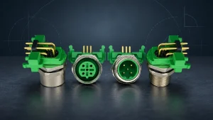
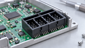
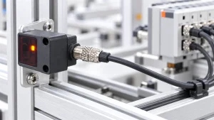
Meet Soulin at electronica 2026 in Munich from November 10 to 13, 2026. Shenzhen Soulin Electronics Technology Co., Ltd. will exhibit at Hall A3, Booth No. 473/6, where our team will discuss custom connector solutions for OEM projects across Automotive Electronics, industrial automation, new energy, IoT, and other electronic applications.
For teams looking for a custom connector manufacturer at electronica 2026, the booth visit can start with a practical question: does your interface need a catalog connector, a small platform modification, or a fully custom design?
Our engineers can review your actual connector application on site. You can bring a drawing, physical sample, pinout, mating part, PCB layout limit, cable route, rating target, operating environment, expected volume, or purchasing and quality requirements. These details help us judge whether an existing product already fits, whether one controlled change can solve the issue, or whether the project needs custom connector development with tooling and sampling review.

2026 Connector Requirements Behind Automotive, Industrial, Energy, and IoT Projects
The 2026 application areas named by electronica include Automotive, Automation, Electro-Mobility, Power Electronics and Energy Technology, Smart Grids/Smart Energy, Smart Home/Building/Infrastructure, and Internet of Things. Visitors from these fields rarely bring the same connector problem to the booth. Some projects need a catalog connector that already matches the drawing, while others need a supplier to adjust an existing platform or develop a custom connector around the equipment interface.
In Automotive Electronics, compact housing space, vibration, thermal cycling, and service downtime affect the connector choice. Industrial automation projects add cabinet routing, field maintenance, EMI/RFI exposure, and moving machinery. New energy and EV-related equipment brings heat, outdoor exposure, BMS signal routing, and communication interfaces. IoT, smart home, and security devices place more pressure on small layouts, fixed cable direction, and repeatable assembly.
We support Automotive Electronics, Industrial Automation, New Energy & Power System, and Smart Home & IoT projects. In these fields, the connector request often comes down to compact equipment layout, cable route, mating side, power or signal requirement, operating environment, inspection evidence, and production volume. For related instrumentation and security monitoring devices, we use the same engineering filter to place the request into catalog selection, platform modification, or custom connector development.
Drawings, Samples, Pinouts, and Operating Limits to Discuss On Site
A part number alone does not show the full connector problem. The drawing fixes dimensions, tolerances, footprint, pitch, and mating geometry. A physical sample exposes latch access, contact position, cable bend space, handling clearance, and mating feel. The pinout separates power, signal, ground, shielding, and unused circuits. Operating limits add current, voltage, temperature, vibration, sealing needs, expected volume, and validation documents to the same picture.
With a fixed 2.54 mm pin-header footprint, the main question is whether the existing pitch, mating height, and PCB layout already match. Poor latch access points to a different issue, because the connector may fit electrically while failing during assembly or service. Exterior camera wiring with an IP-rated circular connector brings sealing path, mating side, cable bend space, contact retention, and inspection evidence into the same review. Taken together, these details separate product selection from a limited platform change or a custom connector development request.
For custom connector service requests, drawings, samples, and application specifications give us the basis for selecting the practical development option before tooling or production planning.
Evaluate Fit, Change Scope, and Tooling Risk Before Custom Development
Before quotation, the interface needs one clear classification. The existing family either matches the equipment, needs one controlled change, or cannot solve the housing, contact, sealing, or tooling requirement.
The drawing, sample, mating side, PCB footprint, cable route, rating target, operating environment, and production expectation separate the fixed interface from the adjustable detail. The table below turns that separation into three practical outcomes.
| Review Point | Catalog Part | Platform Modification | Custom Development |
|---|---|---|---|
| Interface Fit | Rating, footprint, mating geometry, and assembly space already match. Output: matching family to verify. | Existing family fits after one controlled change. Output: change item to confirm. | Existing housing or contact system cannot meet the interface. Output: custom interface review. |
| Change Scope | Drawing and sample validation stay within published options. Next action: confirm exact part drawing and mating side. | Pinout, latch, plating, cable exit, marking, or packaging needs adjustment. Next action: mark the changed feature and revise the drawing. | Mating direction, housing, contact, sealing route, terminal retention, or PCB architecture needs redesign. Next action: define DFM, tooling, and sample acceptance points. |
| Tooling Risk | Main interface stays with existing tooling. Next action: request sample or datasheet. | Limited tooling or process change enters review. Next action: confirm sampling and inspection requirements. | Tooling, DFM, sample acceptance, and production control require deeper review. Next action: prepare tooling-scope discussion. |
The output should be the closest product family for verification, the limited change for drawing update, or the tooling and sampling issue for engineering review.
Catalog Part for a Proven Rating, Footprint, and Mating Geometry
Catalog selection is suitable after the drawing and sample confirm that an existing connector can be mounted, mated, and assembled without changing the equipment interface. We start with the product family that matches the fixed part of the interface. For example, Pin Header Connectors are checked by pitch, row count, mounting orientation, rated current, rated voltage, plating, and mating geometry. Wire-to-Board Connectors bring the review toward conductor type, housing, terminal, latch, cable exit, and PCB header fit. Board-to-Board Connectors add mating height, stacking direction, PCB alignment, and contact stability. For sealed exterior wiring or exposed industrial interfaces, Waterproof Circular Connectors require the mating side, sealing path, cable-end or panel-end structure, and protection rating to match the equipment.
The project can stay in a catalog family when the rating, pitch, footprint, mating geometry, housing size, terminal type, locking method, cable exit, and assembly method match the design. Our work then stays on drawing comparison, sample fit, mating-side confirmation, and product-level validation instead of housing or contact redesign.
Visual similarity only narrows the search. We still need the exact drawing for pitch, current rating, voltage rating, contact layout, material, plating, mating height, packaging, and mating-side confirmation.
Platform Modification for Limited Pinout, Latch, Plating, or Cable Changes
Use platform modification when an existing connector family fits the equipment, but one specific detail prevents catalog selection. The marked drawing or sample note becomes the starting point. The current part reference, required change, and target application condition give our team enough detail to check the change against the existing housing or contact platform.
Our technical team separates adjustable details from core interface changes. Drawing and sample comparison keeps pinout, latch access, cable length, wire exit, plating, marking, packaging, and harness routing in the platform modification range. Housing geometry, contact structure, mating direction, sealing route, and terminal retention point toward custom development instead.
For sampling and quotation, the revised drawing, marked change area, sample or mating part, target quantity, use condition, and inspection requirement need to be settled. From that information, we define the modified drawing, sample plan, and quote scope.
Our custom connector service supports drawing-based customization, sample processing, tailored pitch, plating, packaging, marking, pilot runs, and custom connector quotes. For platform modification, the service stays focused on the changed feature instead of a full housing or contact redesign.
Custom Design When Existing Housings and Contacts Cannot Solve the Interface
Use this checklist to confirm that the request has moved beyond platform modification:
- Enclosure fit: the published housing leaves no usable clearance.
- Mating path: the connector cannot mate in the direction allowed by the PCB layout or assembly process.
- Contact design: retention, density, or mating-force requirements exceed the existing contact structure.
- Sealing path: the required seal changes the housing geometry.
- Cable exit: the cable direction interferes with assembly or service access.
- Terminal retention: the current structure cannot hold the terminal under the required use condition.
- PCB architecture: board edge position or stacking layout requires another terminal arrangement.
For custom design evaluation, we identify the part of the interface that cannot move. The check covers enclosure space, mating path, PCB edge position, contact layout, sealing path, terminal retention, cable exit, and assembly sequence.
The output should define the design direction, the main risks to confirm, and the next drawing or sample action. Tooling, DFM, material choice, stamping, molding, automated assembly, and inspection planning can then be discussed around a defined interface.
Product Family Match and Prototype Checks Before Production Planning
Product family selection tells us what the sample needs to prove before production planning. Board stacking puts mating height and PCB alignment under the microscope. Cable-to-board routing shifts attention to bend space and latch access. Signal interfaces bring continuity, shielding, and contact position into the check. Waterproof mating requires the sealing path and housing fit to match the equipment. Wire harness samples add wire length, label position, strain relief, routing, and connector orientation.
Our PCB and cabling range gives us the comparison base, but real hardware still decides whether the selected family is ready for production planning. On the hardware interface, the sample is checked for mating feel, footprint alignment, latch access, cable bend space, terminal retention, and sealing path. Electrical verification covers continuity, insulation resistance where relevant, and contact stability. Packaging, wire routing, assembly sequence, and inspection points are confirmed after the sample can be handled, mated, and assembled in the intended equipment. IEC 60512-1 provides a generic reference for connector tests and measurements; severity level, acceptance limit, and sequence still come from the part specification and customer equipment requirements.
Fleet telematics gives a concrete reference. Our Automotive Electronics guidance lists IP67 M12/M16 circular connectors for exterior camera links, DIN 41612 and backplane connectors for DVR or telematics control units, RJ45 interfaces for Ethernet and PoE, automotive power connectors, and low-profile board-to-board or wire-to-board connectors inside constrained enclosures. This keeps the example tied to power input, data transmission, board stacking, and harness routing.
Our industrial automation guidance puts vibration, EMI/RFI exposure, cabinet routing, maintenance access, and mating cycle requirements in the foreground. PLCs, servo drives, HMI panels, and industrial robotics can involve DIN 41612 backplanes, rugged circular connectors, shielded RJ45, board-to-board connectors, and pin header arrays.
For New Energy & Power System projects, BMS, EV charging, inverter, and energy storage equipment often combine power routing, signal stability, heat exposure, outdoor installation, and wire harness route in one connector choice. Before sampling or production planning, housing fit, contact position, insulation requirement, cable direction, and mating interface need to match the selected connector family.

Manufacturing Inputs That Change Cost, Sampling, and Scale-Up
Cost, sampling, and scale-up change with the physical revision. A plating change creates a different workload from a new housing. A cable exit change touches assembly and inspection. A revised mating interface may require tooling review, mold planning, terminal review, and sample acceptance criteria.
We manufacture PCB connectors, electrical connectors, wire harnesses, and custom cable assemblies. Our factory process covers connector tooling, mold development, terminal stamping, injection molding, automated assembly, and vision inspection. Our manufacturing capabilities include a 12,000+ m² manufacturing area, 280+ skilled staff and engineers, and 20+ production lines.
For OEM customization projects, our sampling support includes free samples for design validation, standard prototypes in three days, and 48-hour express sampling for select eligible items after the connector family, drawing version, material, plating, sample quantity, and inspection requirements are confirmed. Custom housing, contact redesign, new tooling, or special validation requirements change the schedule before sampling can be committed.
Manufacturing planning changes with the inspection workload. Catalog samples stay close to drawing comparison and fit checks. Platform changes add confirmation for the revised feature. Custom designs need sample acceptance points tied to tooling, material, contact, housing, and assembly control.
Evidence to Request from a Custom Connector Manufacturer Before Tooling Approval
Tooling approval needs a defined connector option, drawing version, sample plan, and quality evidence. A buyer comparing custom connector manufacturers looks for evidence that attaches each claim to the actual part or assembly.
UL Solutions identifies UL 1977 for U.S. component connectors used in data, signal, control, and power applications. IPC/WHMA-A-620 provides process and acceptance requirements for cable and wire harness assemblies. These references help frame the evidence request, while the project still requires its own drawing, sample, and inspection records.
| Project Statement | Evidence to Request | Risk It Controls |
|---|---|---|
| A catalog product fits the application | Datasheet, drawing, sample, mating-side check, rating review | Footprint mismatch, electrical margin gaps, mating failure |
| A platform change solves the constraint | Revised drawing, change summary, sample plan, retained product-family basis | Scope creep, hidden tooling changes, delayed validation |
| A custom design is justified | DFM feedback, tooling scope, material and plating review, sample acceptance criteria | Tooling cost, mold rework, unclear ownership of the interface |
| Quality can be controlled | Inspection plan, material documentation, dimensional checks, electrical and mechanical test records | Production drift, inconsistent batches, field failure risk |
| Volume production can be planned | Annual quantity, packaging route, production capacity review, lead-time discussion | Launch delay, unstable supply, wrong inventory plan |
Before a tooling gate, we prefer one shared file that aligns the drawing revision, mating-side reference, sample quantity, sample acceptance points, inspection method, annual quantity, packaging requirement, and responsible owner from purchasing, engineering, or quality. That file becomes the meeting handoff for quotation, sampling, tooling review, and quality follow-up.
Clear configuration details turn booth notes into a connector family recommendation, sample availability, a quotation basis, datasheet support, and lead-time details. Regulated or high-risk equipment still needs device-level validation from the product owner; our support stays with connector evidence and production-control information.
FAQ
Conclusion
At Hall A3, Booth No. 473/6, our team will focus on the issue that is blocking release: fit, rating, cable route, operating condition, evidence gap, or tooling exposure. The meeting should end with a defined technical route and the information still needed before quotation or tooling approval.
Meet Soulin during electronica 2026 in Munich from November 10 to 13, 2026. For drawing-based customization, platform modification, or custom connector development, contact our engineers before the show or after the booth discussion so we can prepare the next technical step from the same project details.