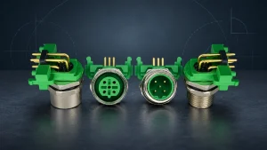
An M5 connector is a compact, screw-locking circular connector used where a sensor or instrument needs a removable electrical connection in limited space. IEC 61076-2-105 covers M5 screw-locking connectors for industrial measurement and control. The M5 × 0.5 mating thread identifies the coupling interface; it does not tell you the overall body size, panel opening, or cable clearance.
Start with the circuit, then work outward through the mating pair, panel hardware, seals, and cable. For procurement, the next step depends on what is already defined: browse existing configurations when the interface is settled, or send the assembly requirements for engineering review when the connector must fit a new enclosure, cable, or production program.
Where an M5 Connector Fits—and When Another Size Makes More Sense
Miniature sensors, precision instruments, and compact industrial controls are useful starting points for M5 selection. Their housings leave little room for external connections, yet technicians still need to disconnect cables for assembly or service. Our M5 panel-mount range includes configurations intended for these applications.
Choose the interface around the electrical duty and the space available for the complete connection. A small receptacle provides little benefit if the cable cannot bend away from it or a technician cannot reach the coupling nut.
| Design requirement | Selection direction |
|---|---|
| A compact sensor connection within the selected M5 model’s ratings | Evaluate M5 and its mating cable or receptacle together. |
| More contacts or greater current capacity than the shortlisted M5 provides | Compare appropriately rated M8 or M12 series. |
| A defined communications protocol | Choose a connector and cable system explicitly specified for that protocol. |
Thread size alone does not establish data capability. Dedicated M5 Single Pair Ethernet products exist, while conventional sensor versions serve different circuit requirements. Select the interface for the intended network and cable system instead of treating all connectors with an M5 thread as electrically equivalent.
Match Pin Count, Mating Side, and Ratings to the Circuit
OurM5 male-and-female panel-mount rangelists 2- to 4-pin configurations. Choose the contact count from the equipment schematic, including supply, return, signal, and any additional circuits. Two, three, or four contacts do not, by themselves, define the function of each pin.
Keep contact gender separate from mounting style. A female panel connector needs a compatible male mating connector, but the contact layout, key orientation, and electrical assignments must also agree. For replacement sourcing, identify the connector already installed in the equipment before selecting its counterpart.
The electrical data should stay attached to an identifiable product. OurM5 Waterproof Male Connector – Panel Mountlists a rated current of 1 A and rated voltage of 60 V. The M5-SW7 rear-lock female model lists the same values. These are ratings for those products, not a definition of every M5 connector on the market.
For example, a design might use three conductors in a four-contact interface. The wiring definition should show the unused position explicitly, without treating it as an extra ground or signal. That simple distinction helps a cable assembler reproduce the intended circuit without guessing.
Use the circuit’s operating requirements to judge those figures. Include the expected load and any startup conditions, then review the rating basis for the intended installation. A connector selected for a low-current sensor should not quietly become a power outlet when the equipment design changes.
A useful procurement record separates the supplier’s part number, contact count, mating-part reference, rated voltage, and rated current. This gives purchasing a clear basis for comparing quotations without turning a general description such as “M5 four-pin waterproof” into the purchase specification.
Read the Panel Drawing Before Choosing the Mount
The mating interface and the panel attachment solve different problems. The coupling joins the two connector halves. The mounting hardware secures one half to the enclosure. A matching M5 interface does not guarantee that two receptacles fit the same opening or occupy the same space behind the panel.
Compare the Installation, Not Just the Connector Face
Our M5-SW7 rear-lock female model is secured from inside the enclosure. That makes internal access part of the installation decision. The male panel-mount product is the long version, so body depth and terminal clearance deserve attention when comparing panel arrangements.
| Existing configuration | What it helps you evaluate | Main installation question |
|---|---|---|
| M5 male panel-mount, long version | A panel interface with male contacts | Is there enough room for the body and internal termination? |
| M5-SW7 rear-lock female | A female interface secured inside the enclosure | Can the assembler reach and tighten the rear hardware? |
| M5 male-and-female panel-mount range | The required contact genders within a panel-connection design | Which part belongs on each side of the intended connection? |
Treat these configurations as candidates for different installations. Match each selected part to its manufacturing drawing, which establishes the cutout, fastening geometry, and installation envelope. A shared M5 designation is not enough to approve a substitution.
Read that drawing in three views. The mating face shows the contact arrangement and orientation. The side view establishes projection on either side of the panel. The section shows how the body, mounting hardware, and sealing surface fit together. Keep the panel cutout beside those views so the enclosure drawing and connector drawing can be reviewed as one assembly.
Front-Lock vs. Rear-Lock Access

For a front-lock arrangement, leave access around the external fastening hardware. For a rear-lock arrangement, allow space inside the enclosure for the nut and the tool used to tighten it. Neither description tells you that the assembled interface will be flush, or that the connector can be replaced without opening the equipment.
For example, consider a compact instrument with a circuit board immediately behind its front panel. A rear-lock female connector may satisfy the circuit and mating requirements, yet the board could obstruct access to the mounting nut. The options are to change the assembly sequence, move the board, or evaluate a different mounting arrangement.
Panel thickness also affects the available thread engagement and the position of the seal. Nearby switches, labels, ribs, and other connectors can restrict tool access even when the body clears the hole. Include those neighboring features in the layout review before releasing the panel for manufacture.
Also distinguish routine cable disconnection from replacing the panel connector itself. A technician may reach the coupling from outside while still needing internal access to remove the receptacle. Planning those two service operations separately avoids selecting a mounting style on an assumption about maintenance.
The practical comparison is therefore broader than hole diameter: cutout shape, body projection, mounting thread, nut position, seal seating, and service access all contribute. Use the selected drawing’s dimensions and tolerances, with its installation instructions, rather than estimating them from the M5 designation or a product photograph.
Evaluate Sealing and Shielding as Installed
Our M5 male panel-mount connector is specified as IP67 when mated. The M5-SW7 rear-lock female connector also has an IP67 rating in the mated condition. Keep that operating state attached to each model when comparing specifications.
With the mounting arrangement established, review the mating interface and the seal against the panel. Include the cable-entry seal wherever the selected assembly has one. Check the mating engagement, seal seating surface, and cable termination together, and specify any protection needed while the port is disconnected.
Describe the exposure in practical terms. State whether the equipment is wiped clean or exposed to cleaning spray, which cleaning agents are used, and how often cleaning takes place. These details give the sealing and material review a clear application to work from.
The male panel-mount connector’s published operating temperature range is −40°C to +105°C. Treat this as the connector’s specification. Select the cable and termination materials for the actual operating temperatures, then establish the range for the complete assembly from the components and construction used.
Shielding is a separate selection decision. For a shielded M5 assembly, define how the cable shield is terminated at the connector and connected to the equipment’s grounding system. Cable construction, shield continuity, grounding, enclosure design, and PCB layout all influence system performance. A metallic-looking housing alone does not establish how well the finished connection will control interference.
Use our waterproof circular connector range to compare available configurations against these sealing and shielding requirements. Carry the selected requirements into the cable and termination specification so the connection is evaluated as one assembly.
Specify Cable and Termination as One Assembly
Follow the connection from the external cable to its destination inside the equipment. Conductor size, cable outside diameter, jacket, length, strain relief, and terminal style all affect that path. Select wire gauge for the circuit and termination, then match cable diameter to the connector entry.
Start with the routing. Where does the cable leave the connector, what must it pass, and does it remain stationary or move during operation? Use the cable manufacturer’s bend-radius requirements and leave room for assembly and service. An alternative exit direction is a requirement to evaluate, not an assumed option on every connector.
Then define the electrical path from end to end. Identify the contact numbers at each interface, the wire connections, and the internal termination. Distinguish between the mating-face view and the termination-side view so the assembly instructions do not depend on someone interpreting a photograph.
Our wire harness and cable assembly services support review from drawings, connection lists, cable requirements, and acceptance criteria. For an M5 project, submit the connector references with the surrounding assembly. This allows the interface and wiring to be evaluated together before the sample is built.
Choose the Purchasing Path That Matches Your Project
A buyer replacing an established component needs a different starting point from an engineer developing a new harness. Keep the request proportionate to the decision: identify an existing configuration first, or describe the assembly that needs to be developed.
Browse Existing M5 Configurations
Browse the M5 waterproof connector range when the mating interface and installation requirements are already known. Compare the relevant M5 connector types by contact count, contact gender, and panel or cable location rather than scanning every item in the range.
For panel procurement, the male long version, rear-lock female, and male-and-female panel range above provide direct starting points. Open the applicable product, record its reference, and request the matching drawing with pricing for the required quantity. Include the intended mating part so the quotation covers the connection you actually need.
Keep the first message simple:
Please quote

Ask whether the quoted item includes the mating half and mounting hardware, or only the connector shown. Compare prices on the same basis: one connector, a mating pair, and a terminated cable assembly are different deliverables. This keeps an apparently lower unit price from obscuring missing parts or assembly work.
An unchanged catalog part does not need an elaborate custom-development brief. Its identity, mating relationship, quantity, and delivery requirement are the essentials for the initial commercial discussion.
Send a Drawing for Engineering Review
Send a drawing for engineering review when your project needs a modified connector, a complete cable assembly, or an OEM configuration with installation and production requirements that extend beyond a catalog part.
Begin with the equipment interface and the change you need. A panel section, connector reference, circuit assignment, cable outline, and expected volume usually make the request easier to evaluate than a long list of preferred features. Separate essential requirements from items that remain open for discussion.
Open the contact form and describe the project in the message field. For drawings and BOM files, use the business email addresses listed on the same page, or exchange them with the assigned contact after the initial inquiry. This keeps the first request simple without leaving the technical documents out of the review.
For example:
- We need an M5 connection for [equipment/application]. The existing interface is [reference], and the required change is [mounting/cable/termination]. We have a panel drawing and wiring specification available. Please review options for [sample quantity] followed by [production forecast], including the proposed tests and any tooling needs.
For a batch program, separate prototype demand from the expected production schedule. Note any labeling, packaging, or inspection-report needs at the beginning. Those details affect what must be quoted and delivered, even when the electrical interface itself remains unchanged.
This gives engineering a defined starting point while allowing purchasing to establish sample cost, development work, and production terms together.
From Selection to an Approved Sample
Once a configuration is shortlisted, the focus shifts from choosing parts to approving them for production.
- Identify the gap. Compare the closest existing configuration with the project requirements. Record what needs to change; where the standard part already meets the brief, retain it.
- Choose the modification route. For changes, use ourOEM customization processto evaluate a cable adjustment, a modified standard component, or new tooling. Agree on the proposed solution and quotation before sampling.
- Define acceptance criteria. Set the test conditions, pass/fail limits, and required reports before evaluating the sample. Include any project-specific compliance documents so engineering and purchasing work from the same approval requirements.
- Evaluate the sample. Assess it in a representative assembly against those criteria. Record the results, address any failures, and repeat the affected checks before approval.
- Freeze the approved configuration. Link the accepted sample to its drawing revision and production specification, including materials, assembly details, labeling, and test requirements. Use that reference for repeat orders, and review subsequent changes for their impact before introducing them into production.
Frequently Asked Questions
The Next Step for Your M5 Project
For an established design, our existing M5 configurations provide a starting point for comparing models and requesting drawings and quotations. The inquiry can focus on the required configuration, quantity, and delivery needs.
A new enclosure, modified connector, or cable assembly calls for engineering review. The panel and wiring requirements define the starting point; the goal is to agree on a proposed configuration and the scope of sample evaluation.

Shenzhen Soulin Electronics Technology Co., Ltd.
Soulin designs and manufactures PCB connectors, circular connectors, and custom wire harnesses for industrial and electronic applications. We help customers source cost-effective alternatives to existing connector models, with support for matching key dimensions, electrical specifications, and application requirements. From standard products to customized interconnect solutions, we support product selection, sample evaluation, and production needs.
View our company page on LinkedIn