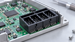
An M12 bulkhead connector is the fixed connection point between a field cable outside a machine and the PCB or wiring inside it. Mounted through the enclosure wall, it keeps the external cable interface in a stable, serviceable position. The same component may also be described as an M12 panel-mount connector, flange socket, panel receptacle, or feed-through connector. Choosing one involves more than matching an M12 cable: the circuit, mounting side, panel opening, seal, rear termination, and cable route all have to fit the same equipment layout. The M12 mating interface alone does not determine the panel cutout, pinout, current rating, or locking method.
What an M12 Bulkhead Connector Controls in the Equipment
That fixed connection spans three physical areas: the external mating face, the enclosure wall, and the internal cable, PCB, or potted termination.
All three areas must work as one assembly. A four-pin connector can be electrically suitable yet impossible to install because the locknut is hidden behind a PCB. The pinout can be correct while the cable exits toward a cabinet frame. Male and female can also be misidentified when they are guessed from the equipment side instead of read from the mating face.
We therefore begin an M12 bulkhead review with the face-view drawing, panel section, and internal layout. Together, they reveal the contact orientation, mounting thread, gasket location, rear clearance, and termination direction.
Front-Lock vs Rear-Lock: Start with Assembly Access
Front-lock and rear-lock designs change how the connector enters the panel and where the securing hardware is tightened. This affects production sequence, field service, enclosure appearance, and tool clearance.
A front-lock design works well when installation or replacement needs to be handled from outside the enclosure. The M12 2-8-pin Y-CJ front-lock panel-mount series uses an external screw-tightening structure. It can simplify final assembly when the internal compartment is already wired or a PCB leaves little room for a wrench.
A rear-lock design places the fastening hardware inside the housing. It suits equipment where the outer panel should remain clean, the hardware should be protected from external access, or maintenance already requires the enclosure to be opened. Rear-locking panel-mount designs such as the M12 SW14T female connector suit equipment where the fastening hardware sits inside the enclosure. For sealed rear exits, potted M16-SW17T female, M16-SW18T male, or PG9-SW17T configurations should be selected according to the panel drawing, rear clearance, and assembly sequence.
The deciding question is whether the connector body, nut, gasket, tools, wires, and nearby components can share the available space during assembly. In a controller with a populated PCB close to the side wall, a rear locknut may become unreachable after the board is fitted. In that layout, the mounting method is wrong before coding or pin count is considered.
Terminology note: Y-CJ is a product-series name. It is unrelated to the standardized Y-coded M12 interface used for combined power and data.
Panel Fit and Body Geometry Must Be Approved Together
"M12" describes the mating interface, not a universal enclosure hole. The panel-mount range includes M12, PG9, and M16 mounting descriptions while the external connection remains M12. Reusing a generic cutout can produce a sample that mates correctly but cannot be fixed to the panel.
The mechanical review should cover panel thickness, cutout size and shape, mounting thread, gasket seat, anti-rotation feature, external projection, rear clearance, and contact-face orientation. These details belong on the approved drawing.
Body geometry then has to follow the space behind the opening. The M12 Waterproof 2~8Pin Panel Mount Male Connector F Type uses a 22L extended-thread housing for panels of varying thicknesses and supports direct PCB assembly. A short-body structure addresses limited internal depth. Right-angle construction redirects the connection when a straight body would point toward a board, door, frame, or adjacent module.
Consider a compact vision controller with a PCB close to the side panel. A straight Ethernet receptacle may fit the cutout but leave the mating cable pressing into the board. The M12 Waterproof 4Pin Panel Mount Right Angle Male/Female Connector uses a D-coded right-angle structure that routes the cable along the equipment side. The elbow only solves the problem when its orientation and termination match the enclosure.
Match the Coding to the Circuit, Then Check the Physical Format
Coding identifies the keyway and helps prevent incompatible M12 interfaces from mating. Pin count describes the contacts within that coded format. Our M12 connector coding guide is a useful starting point, while IEC 61076-2-101 provides the formal standards context for M12 screw-locking circular connectors. Two four-contact connectors can still serve different networks, use different keyways, and carry different pin assignments.
| Circuit or application | Common M12 coding | Engineering checks |
|---|---|---|
| Sensors, actuators, and general I/O | A-coded | Supply and signal assignment, face view, mating cable |
| PROFIBUS and selected fieldbus systems | B-coded | Network specification, shielding, termination |
| 100 Mbps industrial Ethernet | D-coded | Pair routing, cable category, shield continuity |
| Gigabit or 10 Gigabit Ethernet | X-coded | Complete channel performance, shield path, cable type |
| DC power | T-coded or L-coded | Voltage, current per contact, conductor size |
| AC power | S-coded or K-coded | Equipment standard, earth arrangement, spacing |
| Combined power and data | Y-coded | Hybrid pinout and separate power and signal ratings |
Use the table to narrow the coding, then evaluate the connector and mating cable as one channel. For Ethernet, the code sets the mating pattern, while cable category, pair routing, and shield continuity determine whether the installed link reaches the required performance. The panel body still has to fit the available space and cable direction.
The M12 Waterproof 8-Pin Cable End Male Connector, X-Code Front Lock Panel Mount PG9 SW17T is listed with a 30 V rating, 2 A rated current, and IP67/IP68 protection. These values apply to that SW17T configuration, not to every X-coded M12 body or cable assembly.
For power interfaces, coding only narrows the family. Before releasing a part, compare the exact configuration with the circuit voltage, current per contact, conductor size at the selected termination, pin assignment, and operating temperature. If the design sits close to a current or temperature limit, ask for the relevant derating data rather than assuming the headline rating applies under every condition.
More Pins Do Not Increase Current Capacity

Higher contact density gives the designer more circuits within one panel opening. It does not create a higher-power interface.
The M12 2-17-Pin IP68 Waterproof Cable End Male Connector - Front-Locking Panel Mount M12 SW15T provides a clear example. Its published ratings are:
- 2-5 pins: 60 V, 4 A
- 6-8 pins: 30 V, 2 A
- 9-17 pins: 30 V, 1.5 A
A 12-pin or 17-pin version can consolidate several low-current sensor channels, test signals, or control circuits in a compact enclosure. It would be a poor shortcut for an actuator branch that exceeds the 1.5 A rating published for the 9-17-pin configurations.
In our engineering review, each circuit is checked against the rating for the selected contact arrangement. Pin count never replaces load calculations, conductor sizing, or thermal considerations.
IP67/IP68 Starts at the Mating Face and Ends Behind the Panel
Ingress protection is usually discussed through the IP Code defined by IEC 60529, but the installed connector still has to be reviewed as a complete seal. When a panel-mounted connector leaks, the mating face is only one possible entry point. Moisture can also pass between the connector and enclosure or enter through the rear termination.
The sealing path includes the coupled plug and receptacle, the panel gasket or O-ring, and the wire, solder, PCB, or potted area inside the machine. Selected Y-CJ specifications list an EPDM O-ring and IP67/IP68 protection. The finished enclosure still relies on the panel surface, gasket compression, coupling, and assembly quality.
Rear potting protects the cable or terminal exit against moisture, dust, vibration, and pulling forces. It cannot compensate for a damaged gasket or poor mounting surface. An unused outdoor port may also need a protective cap because its sealing condition changes when the connector is unplugged.
Describe the real operating condition in the RFQ: mated during use, opened for service, exposed to washdown, mounted outdoors, or left unused for long periods. That is more useful than requesting a "waterproof connector" without context.
What to Send Before Requesting a Sample
A strong RFQ lets our engineering team review the connector as part of the equipment rather than as an isolated component. If the shown M12 waterproof circular connectors do not cover the exact drawing, the same RFQ can also support custom connector review. Include:
- Equipment type and circuit function
- Required M12 code, contact count, and pin assignment
- Male or female mating face and mating connector reference
- Front-lock or rear-lock assembly preference
- Panel thickness, cutout drawing, mounting thread, and gasket location
- Straight, right-angle, short-body, or extended-thread requirement
- PCB pins, solder cups, flying leads, molded cable, or rear potting
- Voltage and current for each circuit
- Shielding, grounding, cable type, length, and jacket
- Temperature, contaminants, vibration, and required IP condition
- Sample quantity, production volume, labels, packaging, and inspection documents
When the panel section and mating-face drawing arrive early, our engineering team can review the part as an assembly rather than as an isolated connector. The review should catch issues such as a locknut trapped behind the PCB, an elbow facing the wrong direction, or a rear cable bend that exceeds the available depth before a sample is built. We can assess the mounting, termination, sealing, and cable-assembly options; the customer still needs to define the final pinout, whether the panel design can change, and the required protection at equipment level.
Frequently Asked Questions
Conclusion
A good M12 bulkhead choice should leave no hidden question for the first build: the cable should mate, the body should seat, the rear side should clear nearby hardware, and the seal should match the real exposure. If the drawing is still open, share the panel section, mating face, load data, and target quantity before tooling or sampling. Our team can review whether a standard M12 flange socket, a potted rear-lock option, or a modified cable assembly is the cleaner path. Contact us to start that review before the enclosure design is locked.