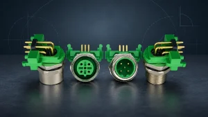
Most waterproof connector failures we help troubleshoot do not start with a bad connector. They start with small assembly mistakes: the wrong cable OD, a strip length that is “close enough,” a half-finished crimp, or a gland seal tightened unevenly.
The reliability of waterproof connectors depends on both crimping quality and sealing control. Based on field-wired M8/M12 assembly troubleshooting, supplier QC checks, and washdown failure reviews, Soulin engineers use a three-layer method that covers cable selection, stripping length, contact inspection, sealing, and final testing.
Tools and Materials You Need
Before crimping a waterproof connector, prepare the connector body, male or female contacts, matching cable, seals, gland nut, backshell, precision wire stripper, ratcheting crimp tool, approved crimp die, continuity tester, inspection light, and the connector datasheet. For production work, also prepare a pull-test fixture and crimp-height measuring tool if the terminal specification requires it.
- Waterproof connector housing, contacts, seals, and gland parts
- Correct cable outside diameter and conductor gauge
- Wire stripper matched to the insulation and conductor size
- Ratcheting crimp tool or approved applicator
- Correct crimp die for the terminal series
- Multimeter or continuity tester
- Inspection light and magnifier
- Pull-test method for quality verification
Our 3-Layer Method for Waterproof Connector Crimping

Our core principle is simple: waterproof connectors can only function reliably if all three layers are correctly configured. These layers are the electrical crimp layer, the mechanical locking layer, and the environmental sealing layer. A defect in any one of these layers can lead to failure in later stages.
| Layer | Inspection item | Failure signal | Verification method |
|---|---|---|---|
| Electrical crimp | Wire gauge, strip length, terminal barrel, conductor position, crimp height | Loose strands, insulation in conductor barrel, distorted contact, high resistance | Visual inspection, crimp-height check, pull-force test, continuity or resistance test |
| Mechanical lock | Contact cavity, retention lance, pinout, coding, mating interface | Contact backs out, wrong cavity, mismating, unstable connection under vibration | Gentle pull-back check, pinout/continuity test, coding check, mating/unmating check |
| Environmental seal | O-ring, gland seal, cable OD, backshell seating, mating condition | Uneven seal compression, exposed copper, loose gland, water, dust, or oil ingress | Verify datasheet OD range, inspect seal line, apply specified torque or hand-tightening, run IP test where required |
Layer 1: Electrical Fit
Strip length lands around 2 to 3 mm on M8 and M12 contacts, with the terminal drawing governing. We release a crimp only when four things show at once.
- Conductor barrel formed in a clean B shape
- A small bell mouth at the rear of the barrel
- A short conductor brush visible at the front
- Insulation crimp gripping the jacket without cutting it
Miss any one and the crimp gets scrapped. We do not adjust it.
Three defects account for most rejects. A terminal that pulls off the wire was under-crimped, from an incomplete tool cycle or an oversized die. Insulation inside the conductor barrel means the strip was too short. A banana-shaped terminal was not sitting flat in the die. And never twist stranded conductors before insertion, since a twisted bundle resists the deformation that forms the cold weld.
Layer 2: Mechanical Lock
Coding gets locked before contacts go in. Confirm code, pin count, and signal type against the M12 coding and pinout guide, since a mis-coded assembly can seal perfectly and still be wrong.
Our retention rule carries no number. After insertion, a light pull-back must produce no perceptible movement at all. A contact that shifts and then re-seats has not engaged its lance, and it will back out under vibration while still passing continuity on the bench.
When a contact does move, we extract it and inspect the cavity along with the contact. A lance deformed on the first attempt will not hold a replacement either.
Layer 3: Environmental Seal
The cable datasheet figure is nominal and jacket diameter drifts between lots, so we measure the actual cable with calipers at three points around the circumference and work from the smallest reading. A cable sitting at the extreme end of a gland’s published range seals on one lot and leaks on the next. We treat that range as an outer boundary, not a usable window.
The seal gets judged by its compression witness line. Open a trial assembly and the mark on the O-ring or gland seal should run continuously around the jacket. Heavy on one side and faint on the other means the cable was not centred when the gland was tightened. That assembly gets rebuilt. Re-torquing an off-centre seal deforms it further.
9-Step Waterproof Connector Crimping Process
The step that sends assemblies back for a rebuild more than any other is Step 3. A gland nut and cable seal that were not slid on before crimping cannot pass over a finished contact, so the harness gets cut apart and started again. The nine steps include selection through final testing.
Step 1: Choose M8 or M12 Before You Crimp

Do not start with the crimp tool. Start with the application. The connector size, pin count, coding, cable diameter, current rating, signal type, and IP rating should be confirmed before any wire is stripped. Use this M8 vs M12 waterproof connector table before selecting contacts or stripping cable. For broader product comparison, review the waterproof circular connector category before locking the BOM.
| Connector size | Typical application | Pin or coding options | Cable diameter or rating checks |
|---|---|---|---|
| M8 waterproof connector | Compact sensor wiring, small actuators, LED equipment, low-current signal wiring | Common 2-pin, 3-pin, 4-pin, and 5-pin options by series | Confirm cable OD range, conductor gauge, current rating, IP rating, and mating style |
| M12 waterproof connector | Automation, field I/O, control boxes, industrial Ethernet, power wiring | A-, D-, X-, S-, T-, L-, and K-coded options depending on signal, data, or power | Confirm cable OD, wire gauge, current/voltage, coding, and IP67/IP68/IP69K environment |
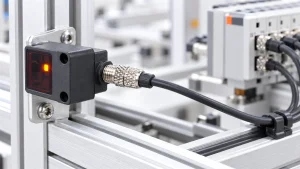
Reach for M8 when the device end has no room for an M12 thread and the circuit is low-current sensor wiring rather than power or data. A 3-wire PNP or NPN sensor needs V+, 0V, and one signal line, so the M8 4-pin waterproof cable end connector Sets carries that circuit with one pin left for a second output or a spare. It is a cable end design, so it gets assembled onto the cable in the field, and the knurled screw and nut let an installer seat the seal by hand in a housing too tight for a wrench. Confirm the cable OD sits inside the gland range before ordering, since that single check decides whether the assembly holds up to washdown, dust, and vibration once installed.
When applications need a more robust industrial interface, match the connector to the installation risk instead of adding multiple product links in one paragraph. For field-assembled automated cabling, a quick-lock M12 cable-end kit helps shorten wiring time while keeping the seal controlled. For high-speed industrial communication, use the M12 IP68 Waterproof 8-Pin Male/Female Connector Set X-CODE when coding, mating accuracy, and IP68 sealing matter more than a general-purpose signal connection. Treat the IP rating as a test condition, not a blanket waterproof promise. IP67 covers dust-tight protection and temporary immersion under IEC 60529, while IP68 must state the tested immersion depth and duration in the connector datasheet or manufacturer test report. For IP69K washdown areas, check ISO 20653:2023 or the manufacturer test report for water temperature, pressure, spray angle, distance, and duration.
Step 2: Before Crimping, Check the Cable OD and Wire Gauge
If the cable OD is too small, the gland will not seal properly. If it is too large, overtightening can deform the seal. Always match the cable OD to the connector’s approved cable range.
The conductor size must also match the contact barrel and crimp die. Do not force a small contact onto a large wire, or use an oversized contact on a small wire. Both can cause weak crimps, poor sealing, and unstable electrical performance.
For field-assembled M12 cabling, the M12 Quick-Lock Waterproof 2~8Pin Cable End Connector Kit helps reduce onsite wiring time while keeping the cable-end connection sealed.
Step 3: Slide on the Gland, Seal, and Backshell First
Before stripping or crimping, slide the gland nut, cable seal, backshell, strain relief, and any heat shrink onto the cable in the correct order. If you forget this step, these parts may not pass over the crimped contact, and the assembly may need to be cut apart and rebuilt.
Check the seal direction before assembly. The seal must sit evenly around the cable jacket. Do not let it press against loose wires, damaged insulation, or the wrong side of the cable seal.
Step 4: Strip the Wire to the Correct Length
Take the strip length from the terminal drawing, not the housing drawing. It sits in the crimp data block next to crimp height and crimp width, and on M8 and M12 contacts it lands near 2 to 3 mm.
Most terminal drawings give that figure without a tolerance. We judge the finished crimp instead. If no conductor brush shows past the front of the barrel, the strip was short. Copper creeping toward the seal area means the opposite, since the bare band between the two crimps has disappeared.
Measure the first piece, then again after any blade change. Damaged strands mean cutting the wire back and stripping fresh. A terminal already crimped onto a bad strip gets scrapped.
Step 5: Position the Contact in the Crimp Tool
Place the terminal in the correct die before inserting the wire. For open-barrel contacts, keep the bare conductor in the conductor crimp area and the insulation under the insulation support.
Insert the wire until the strands sit fully inside the conductor crimp area. Then close the ratcheting crimp tool until it releases. Do not stop halfway because the terminal looks tight. A proper crimp needs full controlled compression.

Step 6: Inspect the Crimp Before Inserting the Contact
Inspect the crimp before putting it into the connector housing. The terminal should be straight, the conductor should be firmly held, the insulation should be supported but not cut, and no wire strands should stick out. If the contact is bent, cracked, twisted, or loose, replace it.
A good crimp should pass these checks: the conductor is fully seated, no insulation is inside the conductor barrel, the terminal is not deformed, and the wire does not pull out under light inspection force. For production work, check crimp height and pull force against the terminal specification. For a wider visual QC reference, use the crimp inspection guide before releasing a batch.
| Check item | Required range | Measured value | Result | Inspector |
|---|---|---|---|---|
| Crimp height | Per terminal drawing, for example 0.95 to 1.05 mm | 0.98 mm | Pass | QC initials and date |
| Pull force | Per terminal drawing, minimum value | Recorded in N | Pass or Fail | QC initials and date |
Step 7: Insert Contacts Into the Correct Cavities
Push each crimped contact into the correct cavity until it locks. Pull back gently on the wire to confirm it stays in place. If it backs out, remove it with the correct extraction tool and inspect the contact and housing. Do not force the connector together.
Also confirm the pinout before sealing. Waterproof does not mean electrically correct. Mark the wire colors, verify the pin assignment, and test continuity. For M12 connectors, choose the correct coding before assembly because A-, D-, X-, S-, T-, L-, and K-coded connectors are used for different signals and power types.
Step 8: Assemble and Tighten the Waterproof Seal
Move the seal, backshell, and gland into place without twisting the wires. Tighten according to the connector datasheet or product instruction.
Do not use the same torque for all M8, M12, quick-lock, panel-mount, or field-wireable connectors. If a torque value is given, use a calibrated tool. If hand tightening is required, stop at the specified seating point.
Overtightening can damage the O-ring or gland seal. Undertightening can leave the seal loose and reduce waterproof performance.
Step 9: Test the Finished Connector
After assembly, test every circuit for continuity. Check for shorts between pins and, if the cable has shielding, between conductors and shield.
Then inspect the seal line. The cable should exit straight, the gland should sit evenly, and no copper should be visible outside the contact or sealing area.
For IP67 or IP68 connectors, remember that the rating only works when the full assembly is correct: the right cable OD, seal position, mating condition, and tightening method.
Standards and Test Records to Confirm
Use IP ratings as test conditions, not a blanket waterproof promise. IEC 60529 IP rating rules define the code used for dust and water ingress, while IP69K washdown requirements should be checked against ISO 20653 or the connector manufacturer’s test report. When you read that report, confirm the exact water temperature, pressure, spray duration, and immersion depth used, since two connectors both labelled IP68 can be tested to very different conditions. For crimp quality, use the terminal drawing, crimp-height window, and pull-force requirement from the contact supplier. IPC/WHMA-A-620 is a useful harness-acceptance reference, but the terminal datasheet remains the pass/fail source.
For production or supplier approval, record the connector part number, cable OD, conductor AWG/mm2, crimp die, tool calibration status, pull-force result, continuity/short test result, and seal inspection result. These records make the assembly traceable instead of relying on a visual check alone.
Why Waterproof Connector Crimping Needs More Than a Good Tool
A waterproof connector fails as a system when crimp quality, contact retention, seal compression, and the matched cable OD do not pass together. A good crimp tool only controls one part of that system. The finished connection still has to mate correctly with connector locks, cable seals, O-rings, and the actual application environment.
Our engineers evaluate waterproof connector assemblies as a complete system. Even if a connector passes a simple continuity test, it may still fail in subsequent tests if the connector doesn’t match the cable diameter, the terminals aren’t fully locked, or the selected M8 or M12 series connector is unsuitable for vibration, washing, immersion, or outdoor environments.
Example Assembly and Test Record: M12 A-Coded Sensor Cable
To demonstrate how these test logs can be used in a real-world assembly process, the following example uses an outdoor automation sensor cable equipped with an M12 Type A coded 4-pin field-connectable waterproof connector. The cable has a polyurethane (PUR) sheath, an outer diameter of 5.8 mm, and a conductor cross-section of 0.34 mm². The finished components should be verified to IP67 under the specified mated-condition test. The inspection record must confirm electrical continuity, as well as cable fit, contact retention force, seal compression, and connection status.
| Inspection item | Recorded result | Test condition/result | Acceptance check |
|---|---|---|---|
| Cable and connector match | 4-conductor PUR cable with 5.8 mm OD used with an M12 A-coded 4-pin waterproof connector | Cable OD checked against the connector seal range before assembly | Cable OD was within the connector gland range, and the connector series matched the application requirement |
| Strip length and conductor position | Wire was stripped according to the terminal drawing, with bare strands fully seated in the conductor barrel | Strip length checked against the terminal drawing before crimping | No exposed copper entered the sealing area, and no insulation was captured inside the conductor crimp |
| Crimp tool and die | Approved ratcheting crimp tool and matching die were used for all four contacts | Full ratchet-cycle crimp completed, with tool calibration status recorded | Each crimp showed no visible contact distortion |
| Contact retention and cavity position | Each crimped contact was inserted into the assigned cavity and checked with a gentle pull-back test | Pull-back check completed after insertion, and cavity position checked against the wiring diagram | Contacts stayed locked in place, and the pinout matched the wiring diagram |
| Electrical test | Continuity passed on all four circuits, and no shorts were found between adjacent pins | Continuity and short-circuit test completed before final sealing | The assembly passed open-circuit and short-circuit checks before final sealing |
| Seal and gland inspection | The cable exited straight from the connector, and the gland was seated evenly around the cable jacket | Visual seal inspection completed after tightening the gland | No twisted seal, exposed copper, uneven compression, or damaged jacket was visible |
| Final mating check | The connector mated smoothly with the matching M12 plug | Mated-condition check completed before installation | Coding, locking, and mating direction were confirmed before installation |
In this example, the documentation confirms that the cable, crimp, contact locking, seals, and mating interface work together as a waterproof connector assembly.
Waterproof Connector Crimping Checklist Before Production
Before building a waterproof connector harness, our engineers recommend confirming these details with the engineering or purchasing team.
| Check item | Why it matters | How to verify |
|---|---|---|
| Connector size and family | M8, M12, or another waterproof circular format changes pin density, locking strength, tool choice, and sealing parts | Compare application load, space, mating interface, and product datasheet before wire prep |
| Pin count and coding | Wrong pin count or coding can cause mismating, wiring errors, or unsupported signal/power use | Confirm schematic, pinout, coding key, and mating connector part number |
| Cable OD and conductor gauge | Seal compression and crimp quality depend on jacket diameter and wire size | Match cable OD range, conductor AWG/mm2, terminal barrel, and crimp die |
| Required IP rating | IP67, IP68, and IP69K are not interchangeable service conditions | Check immersion, washdown, dust, and mating-state requirements against the datasheet |
| Operating environment | Oil, vibration, UV, temperature change, and immersion affect seal material and locking reliability | Review field exposure, cleaning process, bend radius, and vibration profile |
| Assembly type | Cable end, panel mount, flange mount, molded, and field-wireable designs use different parts and workflows | Confirm drawing, BOM, mounting method, backshell, and strain relief before kitting |
| Inspection method | A harness can pass visually but still fail electrically or leak after installation | Define visual inspection, pull test, continuity/short test, crimp-height check, and seal inspection records |
This checklist helps avoid the most common mistake in assembling waterproof connectors: choosing a connector based on the number of pins. The number of pins only tells you how much circuitry a connector can carry, but it doesn’t confirm sealing performance, locking strength, cable compatibility, coding, or long-term field reliability.
FAQ
Final Takeaway
Most waterproof connector failures come from details that look small during assembly, such as a cable OD outside the seal range, a crimp that does not meet the terminal drawing, or a contact that is not fully locked before sealing. These checks matter more than the connector rating printed on the datasheet.
Before installation, confirm the M8 or M12 connector series, pin count, coding, cable jacket diameter, strip length, crimp height, contact retention, gland compression, and final continuity test as one assembly record. If you need help matching cable OD, pin count, coding, and IP rating to a field-assembled waterproof connector, contact Soulin with the drawing, BOM, or harness requirement.
Waterproof Connector Crimping: Production Checks
A reliable waterproof connector crimp needs the correct wire strip length, seal position, terminal crimp height, pull-test result, housing insertion depth and final IP-rated sealing check.
Sourcing next step
- waterproof circular connectors for M8 and M12 projects: Review circular connector options when the assembly needs sealed industrial power, signal or sensor connections.
- custom waterproof connector engineering support: Send the cable OD, pinout, sealing target and old part number for custom or replacement review.
Engineering checklist before RFQ
- Use the terminal drawing to confirm wire range, strip length and crimp tool before production.
- Place the wire seal before crimping and inspect for cuts, compression damage or reversed orientation.
- Run pull, continuity and visual checks before the assembly is approved for the final enclosure.