Meet us at elexcon 2026 in Bao’an, Booth No. 16B17. Before travel, visitors can check the official elexcon exhibitor and product search for the latest exhibitor details. The event is scheduled for September 9-11, 2026, at Shenzhen World Exhibition & Convention Center (Bao’an), with show coverage across embedded electronics, edge AI, automotive electronics, power, sensors, connectors, wire harnesses, and PCB/PCBA.
We will use the meeting to discuss real embedded-device connection problems, not just display products. Visitors can bring PCB layouts, cable-route photos, enclosure limits, existing connector or harness samples, circuit duty, target quantity, and inspection requirements. Our team can place those materials beside the reference part and sort the open questions into quote-ready items and points that still need confirmation, such as mating direction, latch access, cable exit, or enclosure clearance. That keeps each connector discussion tied to the finished device, whether the task involves PCB-level interconnects, internal module wiring, waterproof external interfaces, or organized harness assemblies.

Bring Device Evidence Before Shortlisting Connector Samples
Each connection becomes easier to choose when it is tied to a real device location. A power input beside an enclosure wall, a display cable under a cover, a fan lead beside a removable module, and an external panel port create different fit risks. Electrical requirements describe what the connection carries; the device structure determines insertion path, latch access, routing space, and service clearance after assembly.

| Information to have available | What it clarifies |
|---|---|
| PCB layout, stack drawing, or enclosure height limit | Defines board spacing, mated height, nearby components, and cover clearance |
| Cable-route photo or module-removal path | Reveals bend space, latch access, cable exit direction, and service clearance |
| Existing connector or harness reference, plus mating-side photo | Provides a compatibility baseline before a replacement part is considered |
| Electrical load, target quantity, and inspection requirements | Links the technical choice to quantity, production control, and acceptance criteria |
On site, these details help us check each connector against the actual device. If a latch is hidden, a cable bends into the cover, or the mated height conflicts with the enclosure, the issue can be seen before the request moves to preparation or quotation.
Board-to-Board Connector Fit in Compact PCB Layouts
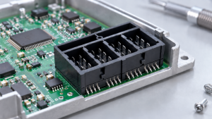
For board-to-board connections, part-number selection should follow the board geometry. With two PCBs inside a compact product, shielding covers, heat sinks, screw posts, component height, support points, and enclosure walls all affect whether the boards can mate cleanly.
Our board-to-board layout options cover stacked, compact, and co-planar arrangements, including mezzanine connectors for parallel board stacking and right-angle connectors for perpendicular layouts.
Connector height, mating direction, guide structure, and handling support should be settled before the layout is frozen or the quotation is issued. Tight board spacing or weak support during mating usually points to a PCB adjustment, not a late part-number change.
Wire-to-Board Selection Around Assembly Access
Wire-to-board selection depends on how the connection will be assembled and released. Even when the current and pitch requirements are correct, the latch can face an enclosure wall, the wire can exit into a removable module path, or the release point can become blocked after PCB installation.
Our wire-to-board connection options cover discrete-wire crimp systems, wafer connector systems, and completed cable assemblies. This lets buyers choose the assembly route first, from loose crimped wires and wafer systems to a finished cable assembly with defined housing, terminal, and conductor requirements.
Check M8 Waterproof Connector Fit Around Cable Exit, Sealing, and Service Access
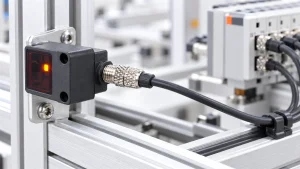
When we review a compact sensor or control module, we look beyond the pin count. We check whether the selected external connector leaves enough space for mating, cable bending, vibration resistance, and service access after the panel and cover are installed. A connector may match the electrical drawing but still create an assembly problem if the cable exit or locking area is blocked.
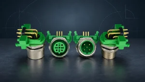
Our M8 waterproof 3-pin cable-end male/female connector with anti-vibration locking is designed for compact sensor wiring, automation modules, machine control equipment, and field signal connections. At the booth, we can review the pin count, mating pair, cable entry direction, panel opening, locking access, bend space, sealing interface, and maintenance clearance with your drawings or samples before sample approval or quotation.
Match External Ports to Panel Opening, Exposure, and Handling
External ports should be judged from the user side of the equipment. A catalog match can still fail when the panel opening is tight, the plug enters at an awkward angle, the cable is pulled during use, or dust, moisture, vibration, and repeated handling change the installed condition.
Our waterproof circular connectors can be narrowed around panel opening, cable exit, sealing exposure, and harness route. For RJ45-style data interfaces, pair this check with our network connectors before quotation. If hand space is limited or the cable pulls against the sealing area, the panel design or harness path may need adjustment before quotation.
| External port topic | What to bring or confirm | Why it affects selection |
|---|---|---|
| Data interface | RJ45-style port position, panel opening, insertion and removal space, strain relief near the cable | The cable plugs in cleanly and avoids pulling force near the port |
| Sealing exposure | Dust, moisture, outdoor or semi-exposed installation, mounting direction, cable exit | The connector body and enclosure opening reduce exposure at the installed position |
| Vehicle or moving equipment | Vibration, locking, mating compatibility, harness route around the module | The port stays stable after installation and repeated handling |
Before the project moves into formal preparation, the port connector should be placed where it will be plugged, pulled, sealed, and serviced. Limited hand space, cable pull near the opening, or conflict with the sealing area means the panel or harness route should be adjusted first.
Fixed-Route Harnesses for Repeatable Wiring
Repeated builds become harder to control when each unit is wired separately. Connector ends, branch positions, labels, sleeves, clips, packaging, and continuity or insulation tests must match the agreed build record.
Our fixed-route harnesses combine separate wires, cables, and connectors into one defined assembly for signal or power transmission. The harness drawing fixes the marking method, protection areas, branch placement, and test requirements before the next build.
A trial route that produces wiring errors, tight bend space, unclear wire IDs, or difficult branch placement points to a finished harness drawing and inspection standard before quotation.
Connector Fit Risks Before Quotation
Quotation should follow confirmation that the selected connector can be inserted, released, routed, and serviced in the final equipment position. Latch access may fail when the release point faces an enclosure wall, even though the electrical requirement is met. Cable routing creates a separate risk near a cover edge: the wire may fit during assembly and become pressed when the cover closes.
These findings may call for a PCB or panel adjustment, a harness drawing, a different standard part, or a clearer validation record before a build or production plan is approved.
Confirm Production and Quality Evidence After the Booth Discussion
After the show conversation, those materials become the basis of a clearer quotation file: application notes, received drawings or photos, checked reference parts, target quantity, testing needs, packaging requirements, and open questions before sampling or production. Buyers also need to know whether the same connector or harness can be produced, inspected, packed, and delivered consistently for follow-up orders. We compare expected quantity, delivery schedule, process stability needs, and inspection requirements with our factory capability and quality records. Together, these pages support a 12,000 m² manufacturing area, automated assembly, vision inspection, ISO 9001, IATF 16949, UL-certified products, RoHS/REACH-compliant products, and quality-process stages from IQC, FQC, OQC, and packaging to finished-goods warehousing and shipment.

FAQs
Conclusion
If PCB spacing, cable routing, enclosure clearance, release access, sealing exposure, or harness repeatability is still blocking the connector choice, settle the issue at elexcon 2026 before quotation or production planning.
For remote follow-up, buyers can share their connector project details with drawings, reference parts, target quantity, and inspection requirements.

Shenzhen Soulin Electronics Technology Co., Ltd.
Soulin designs and manufactures PCB connectors, circular connectors, and custom wire harnesses for industrial and electronic applications. We help customers source cost-effective alternatives to existing connector models, with support for matching key dimensions, electrical specifications, and application requirements. From standard products to customized interconnect solutions, we support product selection, sample evaluation, and production needs.
View our company page on LinkedIn